Adjustment Switches
What is it
Railway adjustment switches (also called breather switches, expansion joints or switch expansion joints) are special track joints that incorporate a controlled gap between rail ends to accommodate thermal expansion and contraction of long welded rails.
They are usually installed at the ends of continuous welded rail (CWR) runs, or between CWR and jointed or structurally independent track, so that rail temperature forces are not directly transmitted into less robust track or adjacent structures.
Why they matter
Adjustment switches protect track from excessive compression and tension forces that could otherwise cause buckling in hot weather or broken rails in cold conditions. They also localise and redistribute thermal forces, preventing those forces from being transmitted into adjoining jointed track or bridges that are not designed for CWR-level longitudinal loads.
Their strengths include:
- Allowing CWR to be used safely across temperature ranges typical of the UK (often ±30 to 35 °C around the stress‑free temperature).
- Providing a defined “stress transition zone” where thermal forces are deliberately reduced to near zero at the interface.
Their weaknesses include:
- Additional complexity, joints and moving interfaces, which can generate higher maintenance demand and local dynamic loads.
- Sensitivity to poor stressing, ballast condition or fastener resistance in the transition length, which can undermine their intended behaviour.
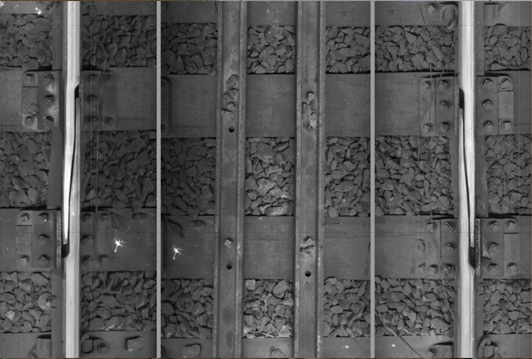
Adjustment switches captured by AIVR for remote inspection.
When: key dates
The concept of intentional expansion joints dates from the early use of metal rails in the 19th century, as engineers moved from short, closely spaced mechanical joints towards longer rails and then CWR. Modern switch‑type expansion joints and breather switches developed alongside CWR technology in the mid‑20th century; detailed design work on “switch expansion joints” appears in contemporary fatigue and structural studies rather than a single named invention.
When they are used
Adjustment switches operate whenever rail temperature departs from the stress‑free temperature: gaps open as rails contract in cold conditions and close (or geometry shifts) as rails expand in heat, within a designed movement range. Their function is continuous, but they become most critical during temperature extremes and following stressing work near the stress transition zone.
Where they are used
Adjustment switches are typically located:
- At each end of long CWR sections where these interface with jointed track.
- Around bridges, viaducts and some tunnels, where track and structure need to expand at different rates or where structure‑borne forces must be isolated.
In the UK, CWR is standard on main lines, and adjustment switches are now mainly retained at CWR–jointed interfaces and some switches and crossings layouts not designed for full CWR stresses.
How they work
An adjustment switch uses specially profiled rails and chairs or fastenings that permit one rail end (or a short rail segment) to move longitudinally relative to its neighbour while still guiding the wheelset safely across the joint. The rail ends are tapered or interlaced so that the wheel encounters a gradual change in running surface rather than a sharp step, and check and guard rails may control wheel path.
In CWR, the adjacent “stress transition zone” is designed so that track longitudinal resistance (from fastenings and ballast) progressively absorbs thermal forces, reducing them to approximately zero at the adjustable joint. As temperature changes, the movable rail in the adjustment switch slides within this arrangement, opening or closing the gap but keeping forces within safe limits and preventing their transmission into adjoining track or structures.